Friday 6 May 2016

Cisco Router&switch


Image Files on the Switch

The Cisco Nexus 5000 Series switches have the following images:
  • BIOS and loader images combined in one file
  • Kickstart image
  • System image that includes a BIOS image that can be upgraded
The switch has flash memory that consists of two separate flash parts:
  • A 2 MB flash part holds two BIOS and loader images.
  • A 1 GB flash part holds configuration files, kickstart images, systems images, and other files.
The upgradeable BIOS and the golden BIOS are programmed onto the 2 MB flash part. You cannot upgrade the golden BIOS.
When you download a new pair of kickstart and system images, you also get a new BIOS image because it is included in the system image. You can use the install all command to upgrade the kickstart, system, and upgradeable BIOS images.
This section includes the following topics:

Starting the Switch

A Cisco Nexus 5000 Series switch starts its boot process as soon as its power cord is connected to an A/C source. The switch does not have a power switch.

Boot Sequence

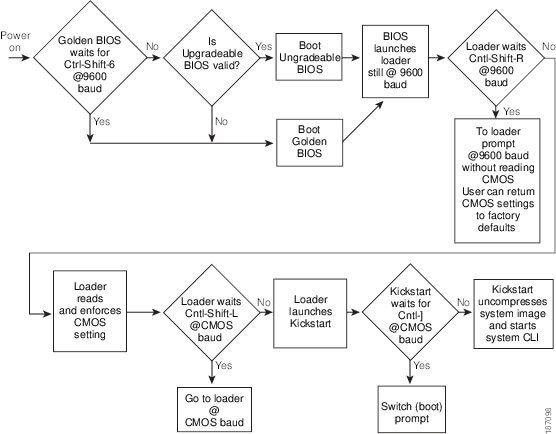
When the switch boots, the golden BIOS validates the checksum of the upgradeable BIOS. If the checksum is valid, then control is transferred to the upgradeable BIOS image. The upgradeable BIOS launches the kickstart image, which then launches the system image. If the checksum of the upgradeable BIOS is not valid, then the golden BIOS launches the kickstart image, which then launches the system image.
You can force the switch to bypass the upgradeable BIOS and use the golden BIOS instead. If you press Ctrl-Shift-6within two seconds of when power is supplied to the switch, the golden BIOS will be used to launch the kickstart image, even if the checksum of the upgradeable BIOS is valid.

Note When you press Ctrl-Shift-6, the console settings must be set to their defaults: 9600 baud, 8 data bits, no parity, and 1 stop bit.

Before the boot sequence starts, the BIOS performs internal tests on the switch. If the tests fail, then the loader does not gain control. Instead, the BIOS image retains control and prints a message to the console at 9600 baud every 30 seconds that indicates a failure.
Figure 1-1 shows the normal and recovery boot sequence.
Figure 1-1 Boot Sequence

For information about recovery procedures, see Chapter1, “Troubleshooting”

Console Settings

The loader, kickstart, and system images have the following factory default console settings:
  • Speed—9600 baud
  • Databits—8 bits per byte
  • Stopbits—1 bit
  • Parity—none
These settings are stored on the switch, and all three images use the stored console settings.
To change a console setting, use the line console command in configuration mode. The following example configures a line console and sets the options for that terminal line:
switch# configure terminal
switch(config)# line console
switch(config-console)# databits 7
switch(config-console)# exec-timeout 30
switch(config-console)# parity even
switch(config-console)# stopbits 2
 
You cannot change the BIOS console settings. These are the same as the default console settings.

Upgrading the Switch


Note Users with the network-admin role can upgrade the software image on the switch.

This section includes the following topics:

Upgrade Procedure Summary

The following summary procedure describes how to upgrade the switch software:

Step 1 Log in to the console port on the supervisor module.
Step 2 Log in to Cisco.com and download the kickstart and system images to a server.
Step 3 Download the kickstart and system images to the switch using the copy command.
Step 4 Install the images using the install all command.

Caution While the switch performs the installation, all traffic through the switch is disrupted.


Detailed Upgrade Procedure


Caution  Upgrading a Cisco Nexus 5000 Series switch disrupts all traffic flow through the switch.

To upgrade the software on the switch, follow these steps:

Step 1 Log in to the switch on the console port connection.
Step 2 Log in to Cisco.com to access the Software Download Center. To log in to Cisco.com, go to the URL http://www.cisco.com/ and click Log In at the top of the page. Enter your Cisco username and password.

Note Unregistered Cisco.com users cannot access the links provided in this document.

Step 3 Access the Software Download Center using this URL:
Step 4 Navigate to the software downloads for Cisco Nexus 5000 Series switches.
You see links to the download images for the switch.
Step 5 Read the release notes for the related image file.
Step 6 Select and download the kickstart and system software files to a server.
Step 7 Ensure that the required space is available in the bootflash: directory for the image file(s) to be copied.
switch# dir bootflash:
5910 Jun 17 14:48:28 2008 config0617
453 Jan 01 00:12:13 2005 ent-fm.lic
453 Jan 01 20:50:55 2005 ent-fm123.lic
453 Jan 01 20:58:49 2005 ent-fm123456.lic
215 Jan 01 00:13:50 2005 enterprise.lic
221 Jan 01 04:25:43 2005 eth-mod.lic
219 Jan 01 04:26:14 2005 eth-port.lic
216 Jan 01 00:21:48 2005 fc-feature.lic
49152 Jul 28 09:42:51 2008 lost+found/
21581824 Jul 08 10:11:14 2008 n5000-uk9-kickstart.4.0.0.N1.1.445.bin
21573632 Jul 28 09:38:33 2008 n5000-uk9-kickstart.4.0.0.N1.1.47.bin
20062208 Jul 28 09:43:05 2008 n5000-uk9-kickstart.4.0.0.N1.2.467.bin
77139580 Jul 08 10:10:45 2008 n5000-uk9.4.0.0.N1.1.445.bin
75270834 Jul 28 09:38:33 2008 n5000-uk9.4.0.0.N1.1.47.bin
76924383 Jul 28 09:44:01 2008 n5000-uk9.4.0.0.N1.2.467.bin
4096 Jan 01 00:07:37 2005 routing-sw/
3697 Apr 30 14:53:07 2008 startup-config
4096 Aug 08 12:49:09 2008 test/
0 Jan 03 04:19:13 2005 thttpd_output
782893 Jan 21 16:56:14 2005 zone-scale-config.out
126927 Jan 21 16:55:45 2005 zoneset-scale-config.out
 
Usage for bootflash://sup-local
855547904 bytes used
6942613504 bytes free
7798161408 bytes total


Tip We recommend that you keep the kickstart and system image files for at least one previous software release to use if the new image files do not load successfully.

Step 8 If you need more space on the active supervisor module bootflash, delete unnecessary files to make space available.
switch# delete bootflash:n5000-uk9-kickstart.4.0.0.N1.1.445.bin
switch# delete bootflash:n5000-uk9.4.0.0.N1.1.445.bin
 
Step 9 Copy the kickstart and system images to the supervisor module bootflash using a transfer protocol. You can useftp:, tftp:scp:, or sftp:. The examples in this procedure use scp:.
switch# copy scp://user@scpserver.cisco.com//downloads/n5000-uk9-kickstart.4.0.0.N1.2.bin bootflash:n5000-uk9-kickstart.4.0.0.N1.2.bin
switch# copy scp://user@scpserver.cisco.com//downloads/n5000-uk9.4.0.0.N1.2.bin bootflash:n5000-uk9.4.0.0.N1.2.bin
 
Step 10 Install the new images, specifying the new image names that you downloaded in step 9.
switch(config)# install all kickstart bootflash:n5000-uk9-kickstart.4.0.0.N1.2.bin system bootflash:n5000-uk9.4.0.0.N1.2.bin
 
The install command performs the following actions:
  • performs compatibility checks (equivalent to the show incompatibility command) for the images that you have specified. If there are compatibility issues, an error message is displayed and the installation does not proceed.
  • Displays the compatibility check results and displays whether the installation is disruptive.
  • Provides a prompt to allow you to continue or abort the installation.

Note A disruptive installation causes traffic disruption while the switch reboots.

  • Updates the boot variables to reference the specified images and saves the configuration to the startup configuration file.
Step 11 After the switch completes the installation, log in and verify that the switch is running the required software version.
switch# show version
Cisco Nexus Operating System (NX-OS) Software
TAC support: http://www.cisco.com/tac
Copyright (c) 2002-2008, Cisco Systems, Inc. All rights reserved.
The copyrights to certain works contained herein are owned by
other third parties and are used and distributed under license.
Some parts of this software may be covered under the GNU Public
License or the GNU Lesser General Public License. A copy of
each such license is available at
http://www.gnu.org/licenses/gpl.html and
http://www.gnu.org/licenses/lgpl.html
 
Software
BIOS: version 1.2.0
kickstart: version 4.0(0)N1(2)
system: version 4.0(0)N1(2)
 
BIOS compile time: 06/19/08
kickstart image file is: bootflash:/n5000-uk9-kickstart.4.0.0.N1.2.467.bin
kickstart compile time: 7/28/2008 2:00:00 [07/28/2008 09:41:24]
system image file is: bootflash:/n5000-uk9.4.0.0.N1.2.467.bin
system compile time: 7/28/2008 2:00:00 [07/28/2008 10:09:17]
 
Hardware
cisco Nexus5020 Chassis ("40x10GE/Supervisor")
Intel(R) Celeron(R) M CPU with 2074164 kB of memory.
Processor Board ID JAB120600AY
 
bootflash: 7864320 kB
 
nms-eugene-02 kernel uptime is 11 days 3 hours 15 minute(s) 19 second(s)
 
Last reset at 63897 usecs after Mon Jul 28 09:46:39 2008
Reason: Reset by installer
System version: 4.0(0)N1(1)
Service:

Downgrading from a Higher Release


Note Only users with the network-admin role can downgrade the software image.

The procedure to downgrade the switch is identical to a switch upgrade, except that the image files to be loaded are for an earlier release than the image currently running on the switch.

Note Prior to downgrading to a specific release, check the release notes for the current release installed on the switch, to ensure that your hardware is compatible with the specific release.

To downgrade the software on the switch, follow these steps:

Step 1 Locate the image files you will use for the downgrade by entering the dir bootflash: command.
If the image files are not stored on the bootflash memory, download the files from Cisco.com (using steps 1 through 9 of the software upgrade procedure).
Step 2 Install the new images.
switch(config)# install all kickstart bootflash:n5000-uk9-kickstart.4.0.0.N1.1a.bin system bootflash:n5000-uk9.4.0.0.N1.1a.bin
 
The install all command performs the following actions:
  • performs compatibility checks (equivalent to the show incompatibility command) for the images that you have specified. If there are compatibility issues, an error message is displayed and the installation does not proceed.
  • Displays the compatibility check results and displays whether the installation is disruptive.
  • Provides a prompt to allow you to continue or abort the installation.

Note A disruptive installation causes traffic disruption while the switch reboots.

  • updates the boot variables to reference the specified images and saves the configuration to the startup configuration file.
Step 3 After the switch completes the installation, log in and verify that the switch is running the required software version.
switch# show version
 

Initial Configuration

The section includes the following topics:

Configuration Prerequisites

The following procedure is a review of the tasks you should have completed during hardware installation. These tasks must be completed before you can configure the switch.
Before you can configure a switch, follow these steps:

Step 1 Verify the following physical connections for the new Cisco Nexus 5000 Series switch:
  • The console port is physically connected to a computer terminal (or terminal server).
  • The management Ethernet port (mgmt0) is connected to an external hub, switch, or router.
Refer to the Cisco Nexus 5000 Series Hardware Installation Guide (for the required product) for more information.

Tip Save the host ID information for future use (for example, to enable licensed features). The host ID information is provided in the Proof of Purchase document that accompanies the switch.

Step 2 Verify that the default console port parameters are identical to those of the computer terminal (or terminal server) attached to the switch console port:
  • 9600 baud
  • 8 data bits
  • No parity
  • 1 stop bit


Initial Setup

The first time that you access a switch in the Cisco Nexus 5000 Series, it runs a setup program that prompts you for the IP address and other configuration information necessary for the switch to communicate over the Ethernet interface. This information is required to configure and manage the switch.

Note The IP address can only be configured from the CLI. When the switch powers up for the first time, you should assign the IP address. After you perform this step, the Cisco MDS 9000 Family Fabric Manager can reach the switch through the console port.

Preparing to Configure the Switch

Before you configure Cisco Nexus 5000 Series switch for the first time, you need the following information:
  • Administrator password.

Note If a password is weak (short, easy-to-decipher), your password configuration is rejected. Be sure to configure a strong password.

  • If you are using an IPv4 address for the management interface, you need the following information:
 IPv4 subnet mask for the switch’s management interface.
 IPv4 address of the default gateway (optional).
  • SSH service on the switch (optional).
To enable this service, select the type of SSH key (dsa/rsa/rsa1) and number of SSH key bits (768 to 2048).
  • NTP server IPv4 address (optional).
  • SNMP community string (optional).
  • Switch name (optional).
This is your switch prompt.
  • An additional login account and password (optional).

Note If you are using IPv4, be sure to configure the IPv4 route, the IPv4 default network address, and the IPv4 default gateway address to enable SNMP access.

Default Login

The switch has the network administrator as a default user (admin). You cannot change the default user at any time.
There is no default password so you must explicitly configure a strong password. If a password is trivial (short, easy-to-decipher), your password configuration is rejected. Be sure to configure a strong password. If you configure and subsequently forget this new password, you have the option to recover this password.

Note If you enter a write erase command and reload the switch, you must reconfigure the default user (admin) password using the setup procedure.

Configuring the Switch

This section describes how to initially configure the switch.

Note Press Ctrl-C at any prompt to skip the remaining configuration options and proceed with what you have configured up to that point. Entering the new password for the administrator is a requirement and cannot be skipped.


Tip If you do not want to answer a previously configured question, or if you want to skip answers to any questions, press Enter. If a default answer is not available (for example, switch name), the switch uses what was previously configured and skips to the next question.

To configure the switch for first time, follow these steps:

Step 1 Ensure that the switch is on. Switches in the Cisco Nexus 5000 Series boot automatically.
Step 2 Enter the new password for the administrator.
Enter the password for admin: password

Tip If a password is weak (short, easy-to-decipher), your password configuration is rejected. Be sure to configure a strong password. Passwords are case-sensitive.

Step 3 Enter yes to enter the setup mode.
This setup utility will guide you through the basic configuration of
the system. Setup configures only enough connectivity for management
of the system.
 
*Note: setup is mainly used for configuring the system initially,
when no configuration is present. So setup always assumes system
defaults and not the current system configuration values.
 
Press Enter at anytime to skip a dialog. Use ctrl-c at anytime
to skip the remaining dialogs.
 
Would you like to enter the basic configuration dialog (yes/no): yes
 
The setup utility guides you through the basic configuration process. Press Ctrl-C at any prompt to end the configuration process.
Step 4 Enter the new password for the administrator (admin is the default).
Enter the password for admin: admin
 
Step 5 Enter yes (no is the default) to create additional accounts.
Create another login account (yes/no) [n]: yes
 
While configuring your initial setup, you can create an additional user account (in the network-admin role) besides the administrator’s account. See the “Configuring RBAC” section for information on default roles and permissions.
a. Enter the user login ID.
Enter the user login ID: user_name
 
b. Enter the user password.
Enter the password for user_name: user-password
 
Step 6 Enter yes (yes is the default) to create an SNMP read-only community string.
Configure read-only SNMP community string (yes/no) [n]: yes
 
SNMP community string: snmp_community
 
Step 7 Enter a name for the switch.

Note The switch name is limited to 32 alphanumeric characters. The default is switch.

Enter the switch name: switch_name
 
Step 8 Enter yes (yes is the default) to configure out-of-band management.
Continue with Out-of-band (mgmt0) management configuration? [yes/no]: yes
 
a. Enter the mgmt0 IPv4 address.
Mgmt0 IPv4 address: ip_address
 
Step 9 Enter yes (yes is the default) to configure the IPv4 default gateway (recommended).
Configure the default-gateway: (yes/no) [y]: yes
 
a. Enter the default gateway IPv4 address.
IPv4 address of the default-gateway: default_gateway
 
Step 10 Enter yes (yes is the default) to enable the Telnet service.
Enable the telnet service? (yes/no) [y]: yes
 
Step 11 Enter yes (no is the default) to enable the SSH service.
Enabled SSH service? (yes/no) [n]: yes
 
Step 12 Enter the SSH key type that you would like to generate.
Type the SSH key you would like to generate (dsa/rsa/rsa1)? dsa
 
Step 13 Enter the number of key bits within the specified range.
Enter the number of key bits? (768 to 2048): 768
 
Step 14 Enter yes (no is the default) to configure the NTP server.
Configure NTP server? (yes/no) [n]: yes
 
a. Enter the NTP server IPv4 address.
NTP server IP address: ntp_server_IP_address
 
Step 15 Enter yes (yes is the default) to configure basic Fibre Channel configurations.
Enter basic FC configurations (yes/no) [n]: yes
 
Step 16 Enter shut (shut is the default) to configure the default Fibre Channel switch port interface to the shut (disabled) state.
Configure default physical FC switchport interface state (shut/noshut) [shut]: shut
 
Step 17 Enter on (on is the default) to configure the switch port trunk mode.
Configure default physical FC switchport trunk mode (on/off/auto) [on]: on
 
Step 18 Enter permit (deny is the default) to deny a default zone policy configuration.
Configure default zone policy (permit/deny) [deny]: permit
 
Permits traffic flow to all members of the default zone.

Note If you are executing the setup script after entering a write erase command, you explicitly must change the default zone policy to permit for VSAN 1 after finishing the script using the following command:

switch(config)# zone default-zone permit vsan 1

Step 19 Enter yes (no is the default) to enable a full zone set distribution.
Enable full zoneset distribution (yes/no) [n]: yes
 
Overrides the switch-wide default for the full zone set distribution feature.
You see the new configuration. Review and edit the configuration that you have just entered.
Step 20 Enter no (no is the default) if you are satisfied with the configuration.
The following configuration will be applied:
username admin password <user-password> role network-admin
snmp-server community snmp_community ro
switchname switch
telnet server enable
ssh key dsa 768 force
ssh server enable
system default switchport shutdown san
system default switchport trunk mode on
system default zone default-zone permit
system default zone distribute full
 
Would you like to edit the configuration? (yes/no) [n]: no
 
Step 21 Enter yes (yes is default) to use and save this configuration:
Use this configuration and save it? (yes/no) [y]: yes
 

Caution If you do not save the configuration at this point, none of your changes are updated the next time the switch is rebooted. Type yes to save the new configuration. This operation ensures that the kickstart and system images are also automatically configured (see “Image Files on the Switch” section).


Changing the Initial Configuration

To make changes to the initial configuration at a later time, enter the setup command in EXEC mode:
switch# setup
 
---- Basic System Configuration Dialog ----
 
This setup utility will guide you through the basic configuration of
the system. Setup configures only enough connectivity for management
of the system.
 
*Note: setup is mainly used for configuring the system initially,
when no configuration is present. So setup always assumes system
defaults and not the current system configuration values.
 
Press Enter at anytime to skip a dialog. Use ctrl-c at anytime
to skip the remaining dialogs.
 
Would you like to enter the basic configuration dialog (yes/no): yes
 
The setup utility guides you through the basic configuration process.

Accessing the Switch

After the initial configuration, you can access the switch in a number of ways:
  • Serial console access—You can use a serial port connection to access the CLI.
  • Out-of-band access—You can use Telnet or SSH to access a Cisco Nexus 5000 Series switch or use the Cisco MDS 9000 Fabric Manager application to connect to the switch using SNMP.

Additional Switch Configuration

This section includes the following topics:

Assigning a Switch Name

Each switch in the network requires a unique name. You can assign names to easily identify the switch by its physical location, its network association, or the organization to which it is deployed. The assigned name is displayed in the command-line prompt. The switch name is limited to 20 alphanumeric characters.

Note This guide refers to a switch in the Cisco Nexus 5000 Series switch as switch, and it uses the switch# prompt.

To change the name of the switch, perform this task:

Command

Purpose
Step 1
switch# configure terminal
Enters configuration mode.
Step 2
switch(config)# switchname myswitch1
myswitch1(config)#
Changes the switch name prompt as specified (myswitch1).
Step 3
myswitch1(config)# no switchname
switch(config)#
Reverts the switch name prompt to its default (switch#).

Configuring Date, Time, and Time Zone

The Cisco Nexus 5000 Series switches use Universal Coordinated Time (UTC), which is the same as Greenwich Mean Time (GMT). To change the default time on the switch, perform this task:


Command

Purpose

switch# clock setHH:MM:SS DD Month YYYY
Sets the default time on the switch. HH represents hours in 24-hour time (15 for 3 P.M.), MM is minutes (58), SS is seconds (09), DD is the date (29), Month is the month in words (February), and YYYY is the year (2008).
The following example sets the time for the switch:
switch# clock set 15:58:09 29 February 2008
Mon Feb 20 15:58:09 UTC 2008
 

Note The clock command changes are saved across system resets.

You can specify a time zone for the switch. To specify the local time without the daylight saving time feature, perform this task:


Command

Purpose
Step 1
switch# configure terminal
Enters configuration mode.
Step 2
switch(config)# clock timezone timezone hours_offset minutes_offset
Sets the time zone. timezone is the three letter time zone (PST for Pacific Standard), the hours offset from UTC (-8 for the PST offset), and minutes offset (needed for time zones such as Newfoundland Standard (NST) or India Standard (IST)).
Step 3
switch(config)# exit
Returns to EXEC mode.
Step 4
switch# show clock
Verifies the time zone configuration.
Step 5
switch# show run
Displays changes made to the time zone configuration along with other configuration information.
The following example sets the time zone to Pacific Standard Time (PST) and offsets the UTC time by negative eight hours and 0 minutes:
switch# configure terminal
switch(config)# clock timezone PST -8 0
 
To disable the local time setting, perform this task:

switch(config)# no clock timezone
Disables the time zone adjustment feature.

Adjusting for Daylight Saving Time or Summer Time

You can configure your switch to adjust for daylight saving time (or summer time). By default, Cisco NX-OS does not automatically adjust for daylight saving time. You must manually configure the switch to adjust to the daylight saving time.
For example, following U.S. standards (defined by the Energy Policy Act of 2005), you can have the switch advance the clock one hour at 2:00 a.m. on the second Sunday in March and move back the clock one hour at 2:00 a.m. on the first Sunday in November. You can also explicitly specify the start and end dates and times and whether or not the time adjustment recurs every year.
To enable the daylight saving time clock adjustment, perform this task:


Command

Purpose
Step 1
switch# configure terminal
Enters configuration mode.
Step 2
switch(config)# clock summer-time timezone start_week start_day start_month start_time end_week end_day end_month end_time offset
Sets the daylight savings time for a specified time zone.
The start and end values are as follows:
    • Week ranging from 1 through 5
    • Day ranging from Sunday through Saturday
    • Month ranging from January through December
The daylight offset ranges from 1 through 1440 minutes, which are added to the start time and deleted time from the end time.
switch(config)# no clock summer-time
Disables the daylight saving time adjustment feature.
Step 3
switch(config)# exit
switch#
Returns to EXEC mode.
Step 4
switch# show running-config | include summer-time
Verifies the time zone configuration.
The following example adjusts the daylight savings time for the U.S. Pacific daylight time by 60 minutes starting the second Sunday in March at 2 a.m. and ending the first Sunday in November at 2 a.m:
switch# configure terminal
switch(config)# clock summer-time PDT 1 Sunday March 02:00 1 Sunday November 02:00 60

NTP Configuration

A Network Time Protocol (NTP) server provides a precise time source (radio clock or atomic clock) to synchronize the system clocks of network devices. NTP is transported over User Datagram Protocol UDP/IP. All NTP communications use Universal Time Coordinated (UTC). An NTP server receives its time from a reference time source, such as a radio clock or atomic clock, attached to the time. NTP distributes this time across the network.
This section includes the following sections:

About NTP

In a large enterprise network, having one time standard for all network devices is critical for management reporting and event logging functions when trying to correlate interacting events logged across multiple devices. Many enterprise customers with extremely mission-critical networks maintain their own stratum-1 NTP source.
Time synchronization happens when several frames are exchanged between clients and servers. The switches in client mode know the address of one or more NTP servers. The servers act as the time source and receive client synchronization requests.
By configuring an IP address as a peer, the switch will obtain and provide time as required. The peer is capable of providing time on its own and is capable of having a server configured. If both these instances point to different time servers, your NTP service is more reliable. Even if the active server link is lost, you can still maintain the right time due to the presence of the peer.

Tip If an active server fails, a configured peer helps in providing the NTP time. Provide a direct NTP server association and configure a peer to ensure backup support if the active server fails.

If you only configure a peer, the most accurate peer takes on the role of the NTP server and the other peer(s) acts as a peer(s).

NTP Configuration Guidelines

The following guidelines apply to all NTP configurations:
  • You should have a peer association with another switch only when you are sure that your clock is reliable (which means that you are a client of a reliable NTP server).
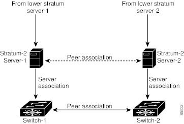
  • A peer configured alone takes on the role of a server and should be used as backup. If you have two servers, then you can have several switches point to one server, and the remaining switches to the other server. You would configure peer association between these two sets, which forces the clock to be more reliable.
  • If you only have one server, it is better for all the switches to have a client association with that server.
Not even a server down time will affect well-configured switches in the network. Figure 1-2 displays a network with two NTP stratum 2 servers and two switches.
Figure 1-2 NTP Peer and Server Association

In this configuration, the switches were configured as follows:
  • Stratum 2 Server 1
 IPv4 address–10.10.10.10
 Stratum–2 Server-2
 IPv4 address–10.10.10.9
  • Switch 1 IPv4 address–10.10.10.1
  • Switch 1 NTP configuration commands
 ntp server 10.10.10.10
 ntp peer 10.10.10.2
  • Switch 2 IPv4 address–10.10.10.2
  • Switch 2 NTP configuration commands
 ntp server 10.10.10.9
 ntp peer 10.10.10.1

Configuring NTP

You can configure NTP using either IPv4 addresses, IPv6 addresses, or Domain Name Services (DNS) names. To configure NTP associations, perform this task:

Command

Purpose
Step 1
switch# configure terminal
Enters configuration mode.
Step 2
switch(config)# ntp server { ip-address | ipv6-address | dns-name}
Forms an association with a server.
Step 3
switch(config)# ntp peer { ip-address | ipv6-address | dns-name}
Forms an association with a peer. You can specify multiple associations.
Step 4
switch(config)# exit
Returns to EXEC mode.
Step 5
switch# copy running-config startup-config
Saves your configuration changes to NVRAM.

Tip This is one instance where you can save the configuration as a result of an NTP configuration change. You can enter this command at any time.
Step 6
switch# show ntp peers
Displays the configured server and peer associations.

NTP CFS Distribution

You can enable NTP fabric distribution for all Cisco Nexus 5000 Series switches in a fabric using the Cisco Fabric Services (CFS). When you perform NTP configurations, and distribution is enabled, the entire server or peer configuration is distributed to all the switches in the fabric.
You automatically acquire a fabric-wide lock when you enter the first configuration command after you enabled distribution in a switch.The NTP application uses an effective and pending database model to store or commit the commands based on your configuration. You changes are stored in the pending database and committed to the effective database.
See the “Information About CFS” section for more information on the CFS application.
This section includes the following sections:

Enabling NTP Distribution

To enable NTP configuration fabric distribution, perform this task:

Command

Purpose
Step 1
switch# configure terminal
Enters configuration mode.
Step 2
switch(config)#ntp distribute
Enables NTP configuration distribution to all switches in the fabric. Acquires a fabric lock and stores all future configuration changes in the pending database.
switch(config)# nontp distribute
Disables (default) NTP configuration distribution to all switches in the fabric.

Committing NTP Configuration Changes

When you commit the NTP configuration changes, the effective database is overwritten by the configuration changes in the pending database and all the switches in the fabric receive the same configuration. When you commit the NTP configuration changes without implementing the session feature, the NTP configurations are distributed to all the switches in the fabric.
To commit the NTP configuration changes, perform this task:

Command

Purpose
Step 1
switch#configure terminal
Enters configuration mode.
Step 2
switch(config)#ntp commit
Distributes the NTP configuration changes to all switches in the fabric and releases the lock. Overwrites the effective database with the changes made to the pending database.

Discarding NTP Configuration Changes

After making the configuration changes, you can choose to discard the changes or to commit them. In either case, the lock is released.
To discard NTP configuration changes, perform this task:

Command

Purpose
Step 1
switch# configure terminal
Enters configuration mode.
Step 2
switch(config)# ntp abort
Discards the NTP configuration changes in the pending database and releases the fabric lock.

Releasing Fabric Session Lock

If you have performed an NTP fabric task and have forgotten to release the lock by either committing or discarding the changes, an administrator can release the lock from any switch in the fabric. If the administrator performs this task, your changes to the pending database are discarded and the fabric lock is released.

Tip The changes are only available in the volatile directory and are subject to being discarded if the switch is restarted.

To use administrative privileges and release a locked NTP session, use the clear ntp session command.
switch# clear ntp session

Database Merge Guidelines

When merging two fabrics, follow these guidelines:
  • Be aware that the merge is a union of the existing and the received database in each switch in the fabric.
  • Do not configure an IP address as a server on one switch and as a peer on another switch. The merge can fail if this configuration exists.
  • Verify that the union of the databases does not exceed the maximum limit of 64.

NTP Session Status Verification

To verify the status of the NTP session, use the s how ntp session-status command.
switch# show ntp session-status
last-action : Distribution Enable Result : Success

Management Interface Configuration

The management interface on the switch allows multiple simultaneous Telnet or SNMP sessions. You can remotely configure the switch through the management interface (mgmt0), but first you must configure some IP parameters so that the switch is reachable. You can manually configure the management interface from the CLI.
This section includes the following sections:

About the mgmt0 Interface

The mgmt0 interface on Cisco NX-OS devices provides out-of-band management, which enables you to manage the device by its IPv4 or IPv6 address. The mgmt0 interface uses 10/100/1000 Ethernet.

Note Before you begin to configure the management interface manually, obtain the switch’s IP address and subnet mask. Also make sure that the console cable is connected to the console port.

Configuring the Management Interface

To configure the management (mgmt0) Ethernet interface to connect over IP, perform this task:

Command

Purpose
Step 1
switch# configure terminal
Enters configuration mode.
Step 2
switch(config)# interface mgmt 0
Selects the management Ethernet interface on the switch and enters interface configuration submode.
Step 3
switch(config-if)# ip address ipv4-address [/ length ]
Configures the IPv4 address and its subnet mask.
switch(config-if)# ip address ipv4-address [subnet-mask ]
An alternative method that configures the IPv4 address and its subnet mask.
switch(config-if)# ipv6 address ipv6-address[ / length ]
Configures the IPv6 address and its subnet mask.
Step 4
switch(config-if)# no shutdown
Enables the interface.
Step 5
switch(config-if)# exit
Returns to configuration mode.
Step 6
switch(config)# vrf context management
Enters VRF context management configuration mode.
Step 7
switch(config-vrf)# ip route ipv4-prefix [ /length ] ipv4-nexthop-address
Configures the IPv4 address of the next hop.
switch(config-vrf)# ipv6 route ipv6-prefix [/ length ] ipv6-nexthop-address
Configures the IPv6 address of the next hop.
Step 8
switch(config-vrf)# exit
Returns to EXEC mode.
Step 9
switch# copy running-config startup-config
(Optional) Saves your configuration changes to the file system.
In some cases, a switch interface might be administratively shut down. You can check the status of an interface at any time by using the show interface mgmt 0 command.

Displaying Management Interface Configuration

To display the management interface configuration, use the show interface mgmt 0 command.
switch# show interface mgmt0
mgmt0 is up
Hardware is GigabitEthernet, address is 000d.ec8f.cb00 (bia 000d.ec8f.cb00)
Internet Address is 172.16.131.202/24
MTU 1500 bytes, BW 0 Kbit, DLY 0 usec,
reliability 255/255, txload 1/255, rxload 1/255
Encapsulation ARPA
full-duplex, 1000 Mb/s
Input flow-control is off, output flow-control is off
8540 packets input, 2835036 bytes
5202 multicast frames, 0 compressed
0 input errors, 0 frame, 0 overrun, 0 fifo
570 packets output, 85555 bytes
0 underrun, 0 output errors, 0 collisions
0 fifo, 0 carrier errors
switch#

Shutting Down the Management Interface

To shut down the management interface (mgmt0), you use the shutdown command. A system prompt requests you confirm your action before it executes the command. You can use the force option to bypass this confirmation. The following example shuts down the interface without using the force option:
switch# configure terminal
switch(config)# interface mgmt 0
switch(config-if)# shutdown
Shutting down this interface will drop all telnet sessions.
Do you wish to continue (y/n)? y
 
The following example shuts down the interface using the force option:
switch# configure terminal
switch(config)# interface mgmt 0
switch(config-if)# shutdown force

Managing the Switch Configuration

This section includes the following topics:

Displaying the Switch Configuration

You can view the ASCII form of the configuration file when required. To view the current configuration tree from the EXEC prompt, enter the show running-config command. If the running configuration is different from the startup configuration, enter the show startup-config command to view the ASCII version of the current startup configuration that was used to boot the switch if a copy running-config startup-config command was not entered after the reboot. Use the show startup-config command to view the contents of the current startup configuration.
You can also gather specific information on the entire switch configuration by entering the relevant show commands. Configurations are displayed based on a specified feature, interface, module, or VSAN. Available show commands for each feature are briefly described in this section and listed at the end of each chapter.

Saving a Configuration

Use the copy running-config startup-config command to save the new configuration into nonvolatile storage. Once this command is entered, the running and the startup copies of the configuration are identical.

Clearing a Configuration

Use the write erase command to clear a startup configuration. Once this command is executed, the switch’s startup configuration reverts to factory defaults. The running configuration is not affected.

Caution  The write erase command erases the entire startup configuration with the exception of any configuration that affects the loader functionality.

The write erase boot command only erases the configuration that affects the loader functionality. The loader functionality configuration includes the boot variables and the mgmt0 IP configuration information (IP address, netmask, and default gateway).
switch# write erase boot
This command will erase the boot variables and the IP configuration of interface mgmt 0.

Using Switch File Systems

This section includes the following topics:

Setting the Current Directory

The cd command changes the current directory level to a specified directory level. The CLI defaults to the volatile: file system. This command expects a directory name input.
Any file saved in the volatile: file system is erased when the switch reboots.
The syntax for this command is cd directory name.
This command exchanges the current directory to the root directory on the bootflash: file system:
switch# cd bootflash:
 
This example changes the current directory to the mystorage directory that resides in the current directory:
switch# cd mystorage

Displaying the Current Directory

The pwd command displays the current directory location. This example changes the directory and displays the current directory:
switch# cd bootflash:
switch# pwd
bootflash:

Listing the Files in a Directory

The dir command displays the contents of the current directory or the specified directory. The syntax for this command is dir directory or dir filename.
This example shows how to list the files on the default volatile: file system:
switch# dir
Usage for volatile: filesystem
0 bytes total used
20971520 bytes free
20971520 bytes available
 

Creating a Directory

The mkdir command creates a directory at the current directory level or at a specified directory level.
The syntax for this command is mkdir directory name.
This example creates a directory called test in the bootflash: directory.
switch# mkdir bootflash:test
 
This example creates a directory called test at the current directory level.
switch# mkdir test

Deleting an Existing Directory

The rmdir command deletes an existing directory at the current directory level or at a specified directory level. The directory must be empty to be deleted.
The syntax for this command is rmdir directory name.
This example deletes the directory called test in the bootflash directory:
switch# rmdir bootflash:test
This is a directory. Do you want to continue (y/n)? [y] y
 
The delete command can also delete empty and non empty directories. When you enter this command, a warning is displayed to confirm your intention to delete the directory.
This example deletes the directory called test at the current directory level:
switch# delete test
This is a directory. Do you want to continue (y/n)? [y] y
 
If the current directory is bootflash:mydir, this command deletes the bootflash:mydir/test directory.

Moving Files

The move command removes a file from the source directory and places it in the destination directory

Caution  If a file with the same name already exists in the destination directory, that file is overwritten by the moved file.

This example moves the file called samplefile from the root directory to the mystorage directory:
switch# move bootflash:samplefile bootflash:mystorage/samplefile
 
This example moves a file from the current directory level:
switch# move samplefile mystorage/samplefile
 
If the current directory is bootflash:mydir, this command moves bootflash:mydir/samplefile to bootflash:mydir/mystorage/samplefile.

Copying Files

The copy command copies a file between file systems within a switch.

Note Use the dir command to ensure that enough space is available in the target file system. If enough space is not available, use the delete command to remove unneeded files.

This example copies the file called samplefile from the root directory to the mystorage directory:
switch# copy bootflash:samplefile bootflash:mystorage/samplefile
 
This example copies a file from the current directory level:
switch# copy samplefile mystorage/samplefile
 
If the current directory is bootflash:mydir, this command copies bootflash:mydir/samplefile to bootflash:mydir/mystorage/samplefile.

Deleting Files

The delete command deletes a specified file or the specified directory and all its contents.
This example shows how to delete a file from the current working directory:
switch# delete dns_config.cfg
 
This example deletes the entire bootflash: directory and all its contents:
switch# delete bootflash:my-dir

Caution  If you specify a directory, the delete command deletes the entire directory and all its contents.

Displaying File Contents

The show file command displays the contents of a specified file in the file system.
This example displays the contents of a file residing in the current directory:
switch# show file myfile

Saving Command Output to a File

You can force all screen output to go to a file by appending > filename to any command. For example, enter show interface > samplefile at the EXEC mode switch prompt to save the interface configuration to samplefile which is a file created at the same directory level. At the EXEC mode switch prompt, enter a dir command to view all files in this directory, including the recently saved samplefile.

Compressing and Uncompressing Files

The gzip command compresses (zips) the specified file using LZ77 coding.
This example directs the output of the show tech-support command to a file (Samplefile), and then zips the file and displays the difference in the space used up in the volatile: directory:
switch# show tech-support > Samplefile
Building Configuration...
switch# dir
1525859 Jul 04 00:51:03 2003 Samplefile
Usage for volatile://
1527808 bytes used
19443712 bytes free
20971520 bytes total
switch# gzip volatile:Samplefile
switch# dir
266069 Jul 04 00:51:03 2003 Samplefile.gz
Usage for volatile://
266240 bytes used
20705280 bytes free
20971520 bytes total
 
The gunzip command uncompresses (unzips) LZ77 coded files.
This example unzips the file that was compressed in the previous example:
switch# gunzip samplefile
switch# dir
1525859 Jul 04 00:51:03 2003 Samplefile
Usage for volatile://
1527808 bytes used
19443712 bytes free
20971520 bytes total
 
Top

Was this Document Helpful?

 Feedback

Viewers of This Document Also Viewed

No comments:

Post a Comment